
Battery Charging Monitor
Introduction
A local manufacturing company contracted me to develop a battery charger monitor. Their forklifts are all battery operated, so they are constantly charging these batteries. Unfortunately, their existing battery charger did not include a means of monitoring the voltage going into the batteries, so they often overcharged and cooked the batteries. Not good. The device I developed monitors the battery’s voltage and when it reaches the “charged” limit automatically switches the charge into trickle charge mode.
There are two additional protections:
- The unit auto-starts at the presence of a battery. It waits an additional three seconds before starting the charger to ensure that battery is fully connected and that the operator has moved away from the contacts.
- Eight hours after the monitor is activated turn off all charging to the battery. This prevents the battery from being cooked by over-charging.
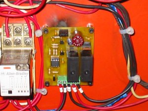
Hardware
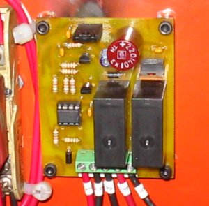
The hardware design is very simple. The controller is a Microchip PIC12F675. It monitors the voltage via it’s analog to digital converter. From there it drives two relays (via transistors) that control the full- and trickle-charges. A built in timer driven by the TMR0 interrupt keeps track of the seconds since activation.
The system is powered from the voltage charge on the battery (28V nominally.) The relays are driven from a 12V regulator, while the PIC is driven from a 5V regulator. The voltage across the battery goes through a resistor divider and then into the PIC’s input. The divider is to keep the input voltage below 5V. I also added a 5.1V zener diode to protect the input should one of the resistors fail.
An Aside about Voltage Regulators
I often need to use voltage regulators in my designs to produce the proper voltages for the micro-controllers. Often I have 24VDC present, but the PIC (or AVR) nominally need 5VDC. I’ve found that going from 24VDC to 5VDC through a regulator like the 7805 does not work very well. The 7805 becomes very hot and then goes into thermal shutdown.
Why does this happen? Ultimately a regulator works by internally dropping the difference between Vin and Vout. By looking at the 7805’s spec sheet you would think you could feed in a maximum of 30VDC while drawing 1.5A and produce a well regulated 5VDC out. If you try it you’ll find out what I did: that it doesn’t work, and you’ll burn your finger if you touch the regulator!
If you read the spec sheet further you’ll find that without a heat-sink a 7805 can dissipate around 6W (max!) at room temperature. Let’s do a little math here. Given:
V(in) = 24VDC
V(out) = 5VDC
The 7805 is, therefore, internally dropping:
V(drop) = V(in) - V(out)
        = 24VDC - 5VDC
        = 19VDC
Now, given the 7805’s power dissipation at room temperature is 6W, how much current can be drawn?
P(room) = 6W
V(drop) = 19VDC
I = P / V
I(max) = P(room) / V(drop)
       = 6W / 19VDC
       = 316mA
Last time I checked, 316mA is well below the 1.5A rating. Also, you’re at the absolute limit of the heat dissipation of the 7805, so you’re likely to toast it if you come anywhere close to drawing 300mA. Hence you either need a good heat-sink, or use some other means of dropping Vin.
Conclusion
Since I implemented and installed this battery charger monitor, the company has reported that they have not had any problems with overcharged batteries, and that their existing batteries are lasting longer. I consider that a success all around.