PICtach
Introduction

In 2004 I finally had to purchase another car since my old boat (a 1980 Oldsmobile Cutlass Supreme) had finally bitten the dust. I looked around and found a 1997 manual 5-speed Chevy Cavalier. Great. It had been a while since I had driven a stick-shift, but I looked forward to it. One problem though: no tach. Now, I don’t actually need a tach to drive stick, but it’s sure nice to have. The project below was my attempt at building a tach for my car.
The project was never finished because in the fall of 2004 I rolled the car. (I survived without a scratch, but the car was totalled.) I did not finish the project because the replacement car already had a built in tach. The code to display the LEDs worked, so I got what I wanted out of the project.
Design

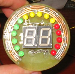
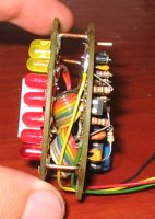
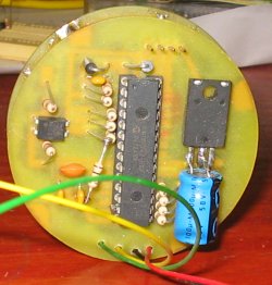
The heart of the pictach is the Microchip PIC18F242. I chose this controller because I had it laying around my work area. The PIC’s spec sheet states that it can sink (or source) 20mA per output pin. That is plenty to drive an LED; however, there are sixteen individual LEDs, plus the seven segments per numeric LED. Now the design decisions begin because first, the PIC doesn’t have that many output pins and second, even if the PIC had that many pins, there is no way it could source (or sink) that much current if all the LEDs were on! (The spec sheet states a total current draw of 300mA.)

To keep the total current draw down, I decided to only illuminate one LED at a time plus one 7-segment LED. Therefore, the total current draw is under 100mA. By rapidly flashing the appropriate LEDs it creates the illusion that they all on at the same time. (Persistent of vision and all that jazz.)
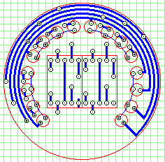
My other design decision was based on multiplexing the LEDs. My PIC did not have sixteen free outputs to drive the various LEDs. I separated the LEDs into four banks of four LEDs. Four output pins connected to the four banks as the return path. The other four output pins from the PIC were connected in parallel to the same LED in each bank. (The first LED in each bank had their anodes connected together.)

To turn on an LED the anode for that position is brought high while the cathode for the bank is driven low. All the other cathode outputs are held high so only the selected LED position from the selected bank is on. Therefore, only eight outputs are needed to drive sixteen LEDs.
The two 7-segment numeric LEDs were wired in a similar manor. The seven segments are connected to seven outputs from the PIC, and each numeric LED has their cathode connected to two more outputs from the PIC. By driving the cathode of the appropriate numeric LED low I can select which numeric LED to display. They are alternated rapidly to give the impression that both were always on.
Firmware
The source code for the tach is written in assembly. This was one of first PIC projects I developed, so it shows the immaturity of my PIC coding style. I would do things differently if I was developing the code now. The pictach source code is released to the public under the GNU Public License.
Conclusion
Perhaps someday I’ll finish this project and package it into a device for a few of my friends. The basic idea works exceedingly well, and I’m pretty pleased with the design.